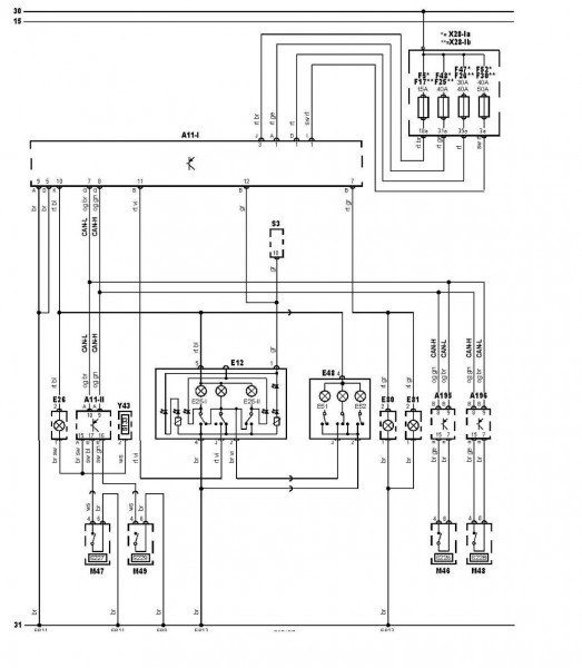
Vt Commodore Ignition Wiring Diagram, Complete Wiring Diagrams For Holden Commodore VT, VX, VY, VZ, VE, VF, 5.36 MB, 03:54, 32,796, John Amahle, 2018-08-01T19:37:41.000000Z, 19, Vt Commodore Ignition Wiring Diagram, to-ja-to-ty-to-my-to-nasz-swiat.blogspot.com, 1272 x 1800, jpeg, bcm pcm 12j swiat nasz, 20, vt-commodore-ignition-wiring-diagram, Anime Arts
In particular i am looking for a wiring diagram for bub engined mk5 golf r32, or at least the pin outs for the cam position sensors. They are the grey 3 pin sensors not the black ones as found in the mk4 engine. I assume the pins are a gnd, signal and a reference voltage although not sure if it is a 5 or 12v feed. Technical and wiring diagrams.
Basically, i need to figure out which pin is ground and which pin is the switched connection for the sidelights, i basically need to wire in a second sidelight. Mkv golf 1. 9tdi sport in dbp, 160,000 miles and climbing! Fuse box on left in engine compartment golf 5. Fuse box diagram type 1. Ignition main circuits relay 2. Vehicle electrics > electrical system > wiring > main fuse holder, golf r32 only. Main fuse holder, golf r32 only : In the golf r32, the starter battery is installed in the luggage compartment. → current flow diagrams, electrical fault finding and fitting locations vehicle electrics > electrical system > wiring > main fuse.
Unique Vw Golf Mk5 Headlight Wiring Diagram #diagram #diagramsample #diagramtemplate #wiringdia

VW Golf 5&6 (TFSI) - waterinjection.info
New Vw Golf Mk5 Rear Light Wiring Diagram | Ac wiring, Diagram, Volkswagen

Where Is The Fuse Box On A Vw Golf Mk5 | Wire

Vw Golf Mk5 Wiring Diagram

Mk5 Golf Tailgate Wiring Diagram - ANCESTRINSIDER

[Mk5 Golf] Wiring diagram for xenon retrofit - Audio, Electrics and Lighting - uk-mkivs
Golf Mk5 Tow Bar Wiring Diagram - easywiring

VW Golf 5&6 (TFSI) - waterinjection.info
Vw Golf Mk5 Wiring Diagram Pdf | schematic and wiring diagram

